The previous article, MRC and the Future of AI Networking, framed MRC as a way to split one large transport domain into multiple reliable lanes, distributing pressure across paths, buffers, and switching resources.
This article starts from that transport view and asks a topology question: what does MRC-style breakout change when AI clusters grow toward zettascale?
The magic of MRC: rephrasing scaling
Most people explain MRC from the transport side: multipath reliable connection, packet spraying, out-of-order placement, congestion control, failure handling, and better load balancing. That is right, but incomplete.
MRC is not only a transport improvement. It changes how we think about GPU cluster scaling. Traditionally, one GPU with one 800G NIC looks like one big pipe:
With MRC-style breakout, the same 800G NIC can become multiple coordinated rails:
Or it can be exposed as two 400G rails, or eight 100G rails. The total bandwidth is still 800G, but the topology is no longer the same.
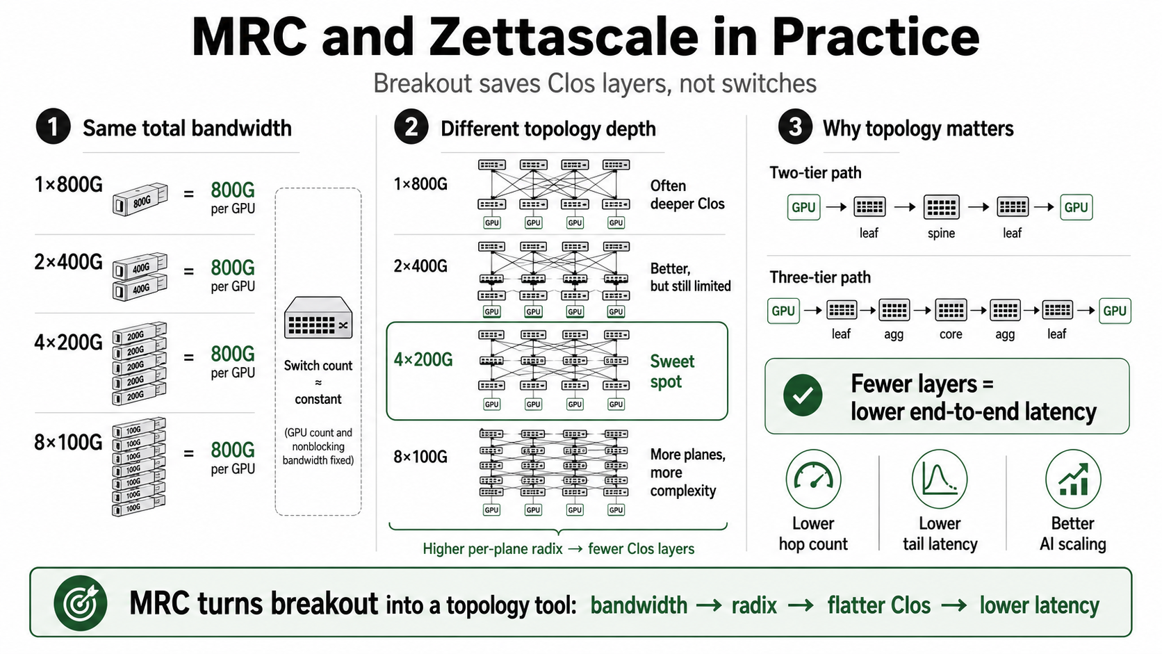
The first question: 1 x 800G, 2 x 400G, 4 x 200G, or 8 x 100G?
Suppose each GPU has one 800G NIC. That NIC can be exposed in several ways:
At the bandwidth level, they look the same. At the topology level, they are very different.
Using a 51.2T switch ASIC as the building block, the same ASIC can be viewed as:
When we lower the per-plane link speed, the same switch ASIC gives more ports. More ports means higher radix. Higher radix means a larger fabric plane can stay flat before it needs another Clos layer.
This is the first-principles reason breakout matters. It is not only a port-mode decision. It is a topology-depth decision.
Maximum scalability for each breakout mode
For simplicity, assume a 51.2T switch ASIC, one 800G NIC per GPU, a 1:1 nonblocking fabric target, parallel or bundled links between switch stages, and bandwidth-minimal switch count rather than vendor SKU-specific construction.
Here R is the port count of one 51.2T switch at the per-plane link speed.
Maximum GPU scalability by breakout mode
| Breakout mode | Planes | Per-plane speed | Ports per switch | One-layer max GPUs | Two-layer max GPUs | Three-layer max GPUs |
|---|---|---|---|---|---|---|
| 1 x 800G | 1 | 800G | 64 | 64 | 2,048 | 65,536 |
| 2 x 400G | 2 | 400G | 128 | 128 | 8,192 | 524,288 |
| 4 x 200G | 4 | 200G | 256 | 256 | 32,768 | 4,194,304 |
| 8 x 100G | 8 | 100G | 512 | 512 | 131,072 | 33,554,432 |
This table is the core of the article. It shows how four breakout choices create four different topology envelopes. The better question is not which breakout is universally best. The better question is: at my target GPU count, which breakout keeps the fabric at the shallowest practical Clos depth while keeping plane count and operations manageable?
Switch count is determined by Clos layer
For a fixed number of GPUs, fixed 800G bandwidth per GPU, fixed oversubscription ratio, and fixed Clos layer count, total switch bandwidth requirement is mostly fixed.
If the fabric is nonblocking, the network must carry this bandwidth. So if we compare 1 x 800G, 2 x 400G, 4 x 200G, and 8 x 100G under the same Clos depth, total switch count is roughly the same.
Once the required Clos layer changes, switch count, latency, and operational complexity change. That is where MRC breakout becomes powerful.
Three GPU cluster sizes: 512, 16K, and 262K GPUs
Let us compare three cluster sizes under the same simplified assumptions: one 800G NIC per GPU, a 51.2T switch ASIC, and a 1:1 nonblocking fabric target.
Small cluster: 512 GPUs
At 512 GPUs, breakout choice already matters. For 1 x 800G, 2 x 400G, and 4 x 200G, one switch plane does not have enough radix to connect all 512 GPUs directly.
So these modes need a two-layer Clos. But 8 x 100G is different: one 100G plane switch can connect all 512 GPUs directly. Since 8 x 100G has eight planes, the design needs one switch per plane, or eight switches total.
512-GPU simplified topology comparison
| Breakout mode | Planes | Required topology | Total switches | Saving vs 1 x 800G | Meaning |
|---|---|---|---|---|---|
| 1 x 800G | 1 | 2-layer Clos | 24 | baseline | 64-port radix is too small for one layer. |
| 2 x 400G | 2 | 2-layer Clos | 24 | 0 | 128-port radix is still too small. |
| 4 x 200G | 4 | 2-layer Clos | 24 | 0 | 256-port radix is still too small. |
| 8 x 100G | 8 | 1-layer per plane | 8 | 16 / 66.7% | 512-port radix exactly fits 512 GPUs. |
At small scale, 8 x 100G saves many switches because it turns the fabric into single-stage planes. The tradeoff is eight rails per GPU and eight planes to manage.
Middle-large cluster: 16,384 GPUs
At 16K GPUs, the story changes. A 1 x 800G fabric plane cannot stay in two layers with a 51.2T switch. 2 x 400G is better, but still not enough. 4 x 200G and 8 x 100G can stay in two layers.
16,384-GPU simplified topology comparison
| Breakout mode | Planes | Required topology | Total switches | Saving vs 1 x 800G | Meaning |
|---|---|---|---|---|---|
| 1 x 800G | 1 | 3-layer Clos | 1,280 | baseline | One large 800G plane lacks radix. |
| 2 x 400G | 2 | 3-layer Clos | 1,280 | 0 | Better, but still not enough. |
| 4 x 200G | 4 | 2-layer Clos | 768 | 512 / 40% | Saves one Clos layer. |
| 8 x 100G | 8 | 2-layer Clos | 768 | 512 / 40% | Same switch saving, but twice the planes. |
This is the most important middle-scale case. It does not win because it saves bandwidth. It wins because it keeps the fabric in two layers.
The difference between 4 x 200G and 8 x 100G is not switch count at this size. Both stay in two layers. Both use 768 switches in this simplified model. The difference is plane count and operational complexity.
At middle-large scale, the best breakout is the one that saves the Clos layer without creating unnecessary plane complexity.
Really large cluster: 262,144 GPUs
At 262K GPUs, the design enters another regime. 1 x 800G simply runs out of radix under the simplified three-layer model.
It would require a deeper hierarchy, multiple fabric blocks, or another architectural workaround. Breakout changes the result.
262,144-GPU simplified topology comparison
| Breakout mode | Planes | Required topology | Total switches | Meaning |
|---|---|---|---|---|
| 1 x 800G | 1 | More than 3-layer / multiple blocks | Not comparable | 800G radix runs out. |
| 2 x 400G | 2 | 3-layer Clos | 20,480 | Fits, but only two planes. |
| 4 x 200G | 4 | 3-layer Clos | 20,480 | Fits with moderate plane count. |
| 8 x 100G | 8 | 3-layer Clos | 20,480 | Fits with smaller planes, but more operations. |
At this scale, breakout is no longer just optimization. It becomes the reason the fabric can still fit into a reasonable three-layer design.
Why fewer Clos layers mean lower latency
Topology matters because every Clos tier adds hops.
A one-layer plane is direct:
A two-tier path looks like this:
A three-tier path looks like this:
A deeper hierarchy adds even more forwarding stages. More switch stages mean more forwarding latency, more serialization points, more queueing opportunities, more congestion interaction, more failure surfaces, and more telemetry complexity.
For AI training and inference, this is especially important because the network is inside the computation loop. All-reduce, reduce-scatter, all-gather, MoE all-to-all, tensor-parallel synchronization, pipeline bubbles, checkpoint movement, KV-cache movement, and distributed inference routing all feel topology.
These workloads do not only care about average bandwidth. They care about tail latency. A single slow communication phase can delay the whole training step or inference pipeline.
Economics and performance of breakout MRC
MRC breakout is not only a way to build larger clusters. It is a way to improve the economics and performance of useful bandwidth.
For a fixed GPU cluster, total endpoint bandwidth may be the same:
But the economic result can be very different because topology is different. A deeper Clos fabric costs more switch stages, optics, cables, racks, power, cooling, failure domains, operational complexity, and latency.
If 8 x 100G keeps a 512-GPU cluster in one layer instead of two, the benefit is direct:
If 4 x 200G or 8 x 100G keeps a 16K-GPU cluster in two layers instead of three, the benefit is also direct:
If breakout keeps a 262K-GPU cluster inside a three-layer design while 1 x 800G runs out of radix, the benefit is more fundamental: breakout becomes required for practical topology scaling.
But maximum breakout is not automatically best. Too few planes may not provide enough radix. Too many planes increase NIC rails, cabling, MRC path state, packet reordering pressure, congestion-control complexity, telemetry objects, and debugging surface.
The best design balances scalability, latency, switch count, plane count, operations, failure isolation, transport complexity, and cost.
Conclusion
MRC is often introduced as a scalability feature. That is true. But the deeper point is that MRC also becomes a topology, latency, and economics feature.
Once MRC can recombine multiple physical rails into one reliable transport abstraction, breakout becomes a topology design tool.
The benefit changes by scale. At 512 GPUs, 8 x 100G can save many switches by avoiding Clos entirely. At 16K GPUs, 4 x 200G and 8 x 100G can both save one Clos layer versus 1 x 800G or 2 x 400G. At 262K GPUs, 1 x 800G cannot fit the simplified three-layer model, so breakout becomes necessary for practical zettascale topology.
In zettascale AI infrastructure, the network is no longer just a packet delivery system. The network becomes part of the distributed computer itself. In that computer, the right breakout choice depends on scale, latency, cost, and operational complexity.
References
- Oracle Cloud Infrastructure Blog: First Principles - Unlocking Oracle Acceleron Multiplanar Fabric with Multipath Reliable Connection
- Oracle Cloud Infrastructure Blog: Zettascale in Practice - Scaling Beyond Limits
- OpenAI: Supercomputer Networking to Accelerate Large-Scale AI Training
- Open Compute Project: Multipath Reliable Connection Specification
- Broadcom: Enabling AI Networking at Scale with Multi-path Reliable Connections